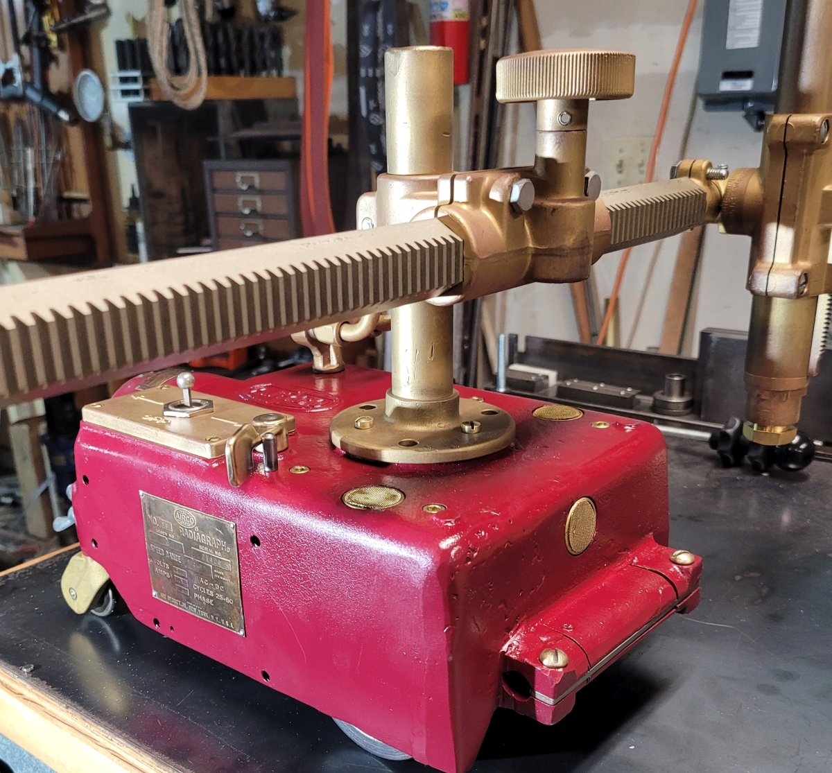
Let me digress briefly. The no. 10 Radiagraph came with two types of rack (the cross-bar which holds the torch out to the side of the machine). They either have a round rack or a hex rack. As is evident in the above photo, this machine's rack is hexagonal. Both types (round and hex) seem very solid and functional to me, but perhaps the hex rack is slightly more rigid. The material the rack is made of appears to be Monel.
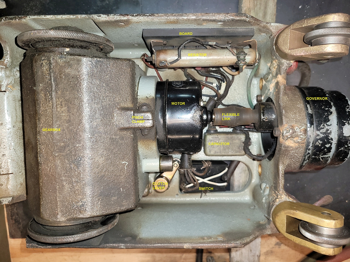
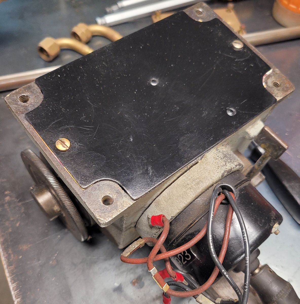
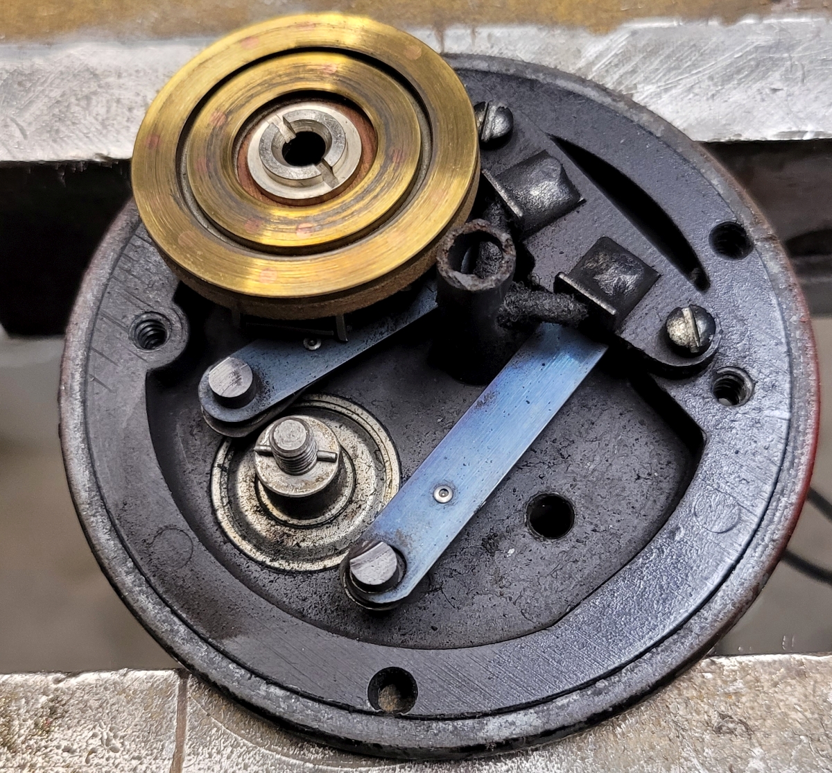
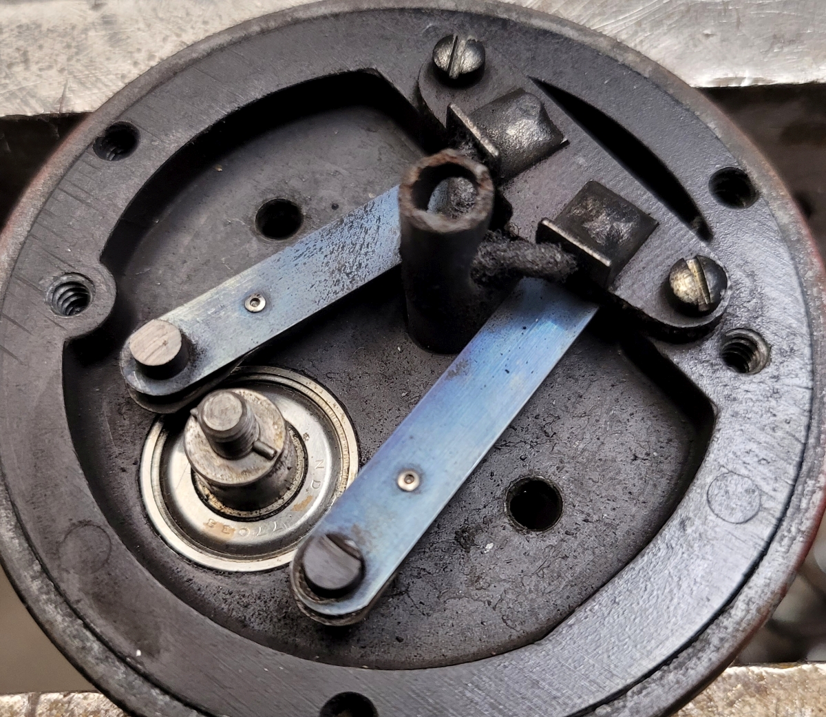
The next thing I did was to turn the machine upside down and set it on two wood blocks. I removed two small screws and this let me take off the bottom pan. Below is a shot of the inside of the machine with labels.
Next, I removed the two small capacitor screws and let the capacitor sit loose. Then I loosened the governor end of the flexible link (coupling the governor and motor shafts) and removed the 3 socket head cap screws which hold the governor in place. After that I was able to pull the governor and capacitor loose as a single assembly. They were still attached to the terminal board.
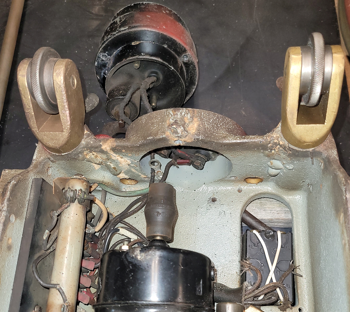
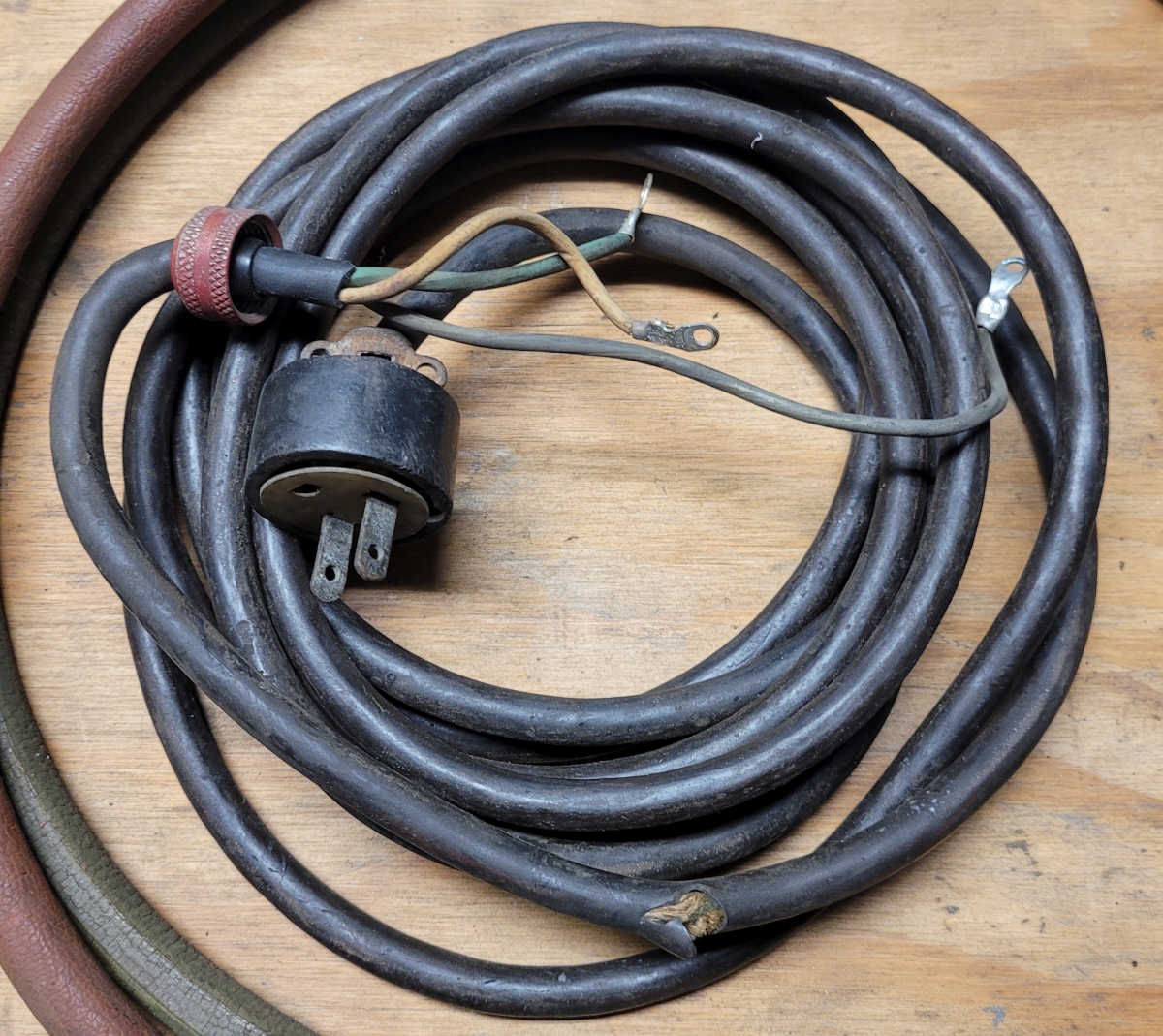
Then I removed two screws from the side of the machine which let the terminal board move loosely inside the machine. Then I removed all of the wiring from the board and replaced the screws to keep track of them. After this, the governor and attached capacitor were free of the machine. Also, after undoing the cord grip I removed the power cord. As the next image shows, the cord does not have a grounded plug and its insulation is damaged.
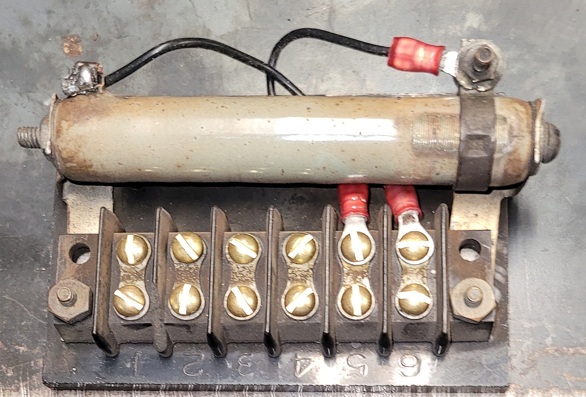
After that I removed the terminal board itself, with the resistor still attached. Notice the cracked insulation on the resistor wiring.
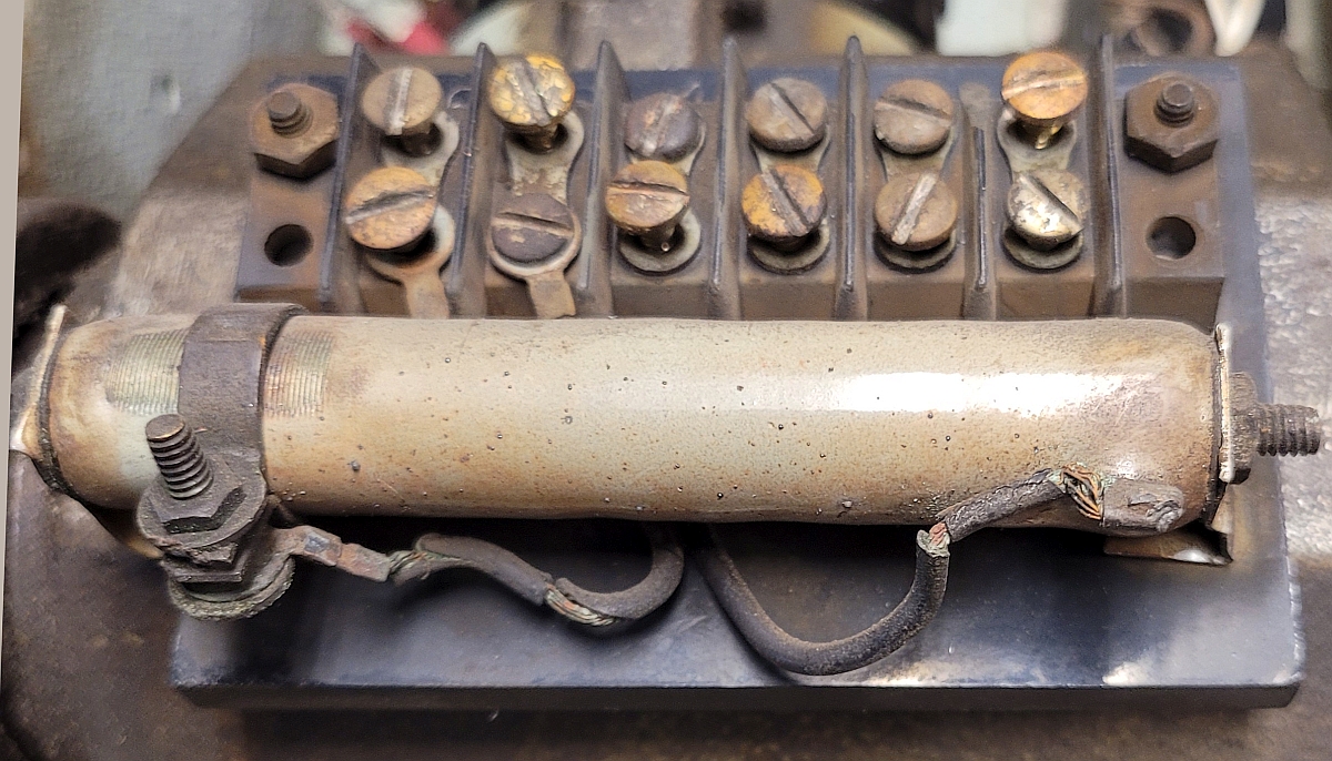
The resistor is nominally 300 ohms. The left wiring lug can slide, adjusting the resistance. You can see how the insulation has been ground away.
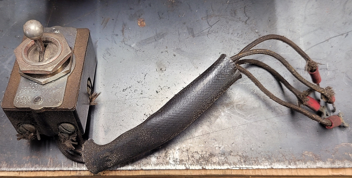
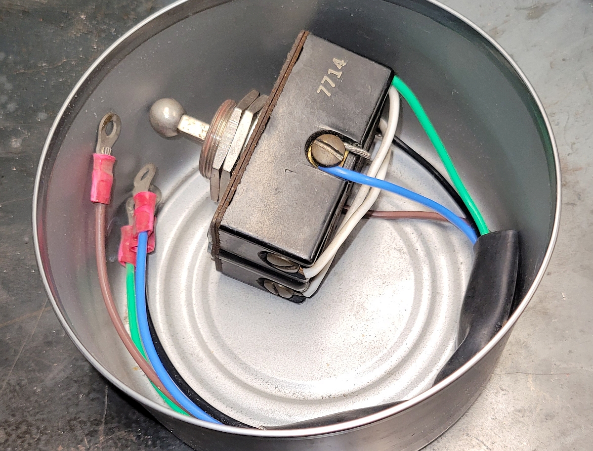
With the terminal board wiring disconnected, the switch was free to remove. These switches are expensive to replace and last a very long time. This one is in good working order so there is no reason to replace it.
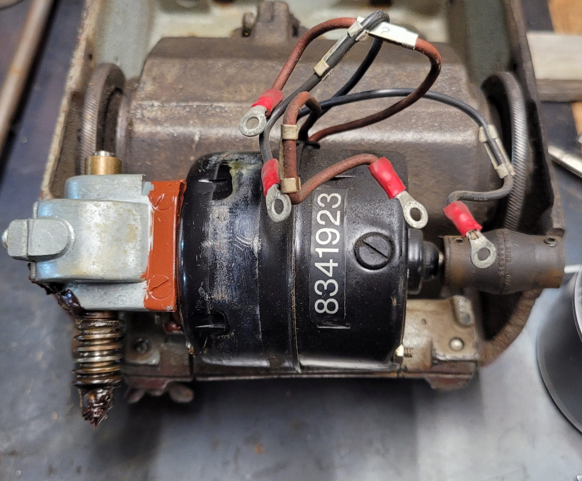
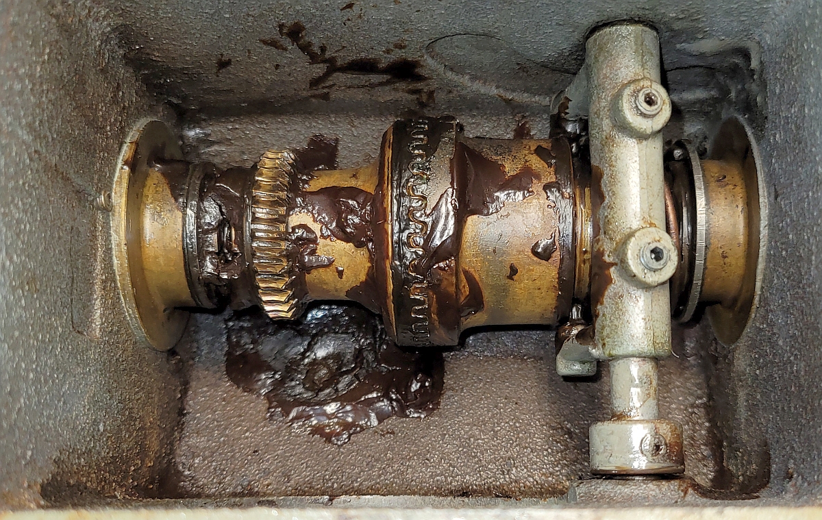
With its wiring disconnected, I loosened the pinch bolt which holds the motor to the transmission and was then able to remove the motor, shaft still connected to the flexible link. Note the grease on the worm - it had fully hardened.
With the motor separated from the gearbox, I removed 4 socket head cap screws from the top of the machine and then removed the gearbox complete with shift lever and drive wheels. There is a flat sheet metal cover on top of the gearbox along with quite a bit of accumulated dirt.
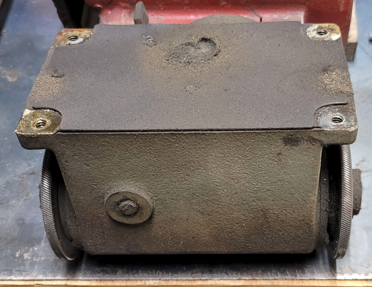
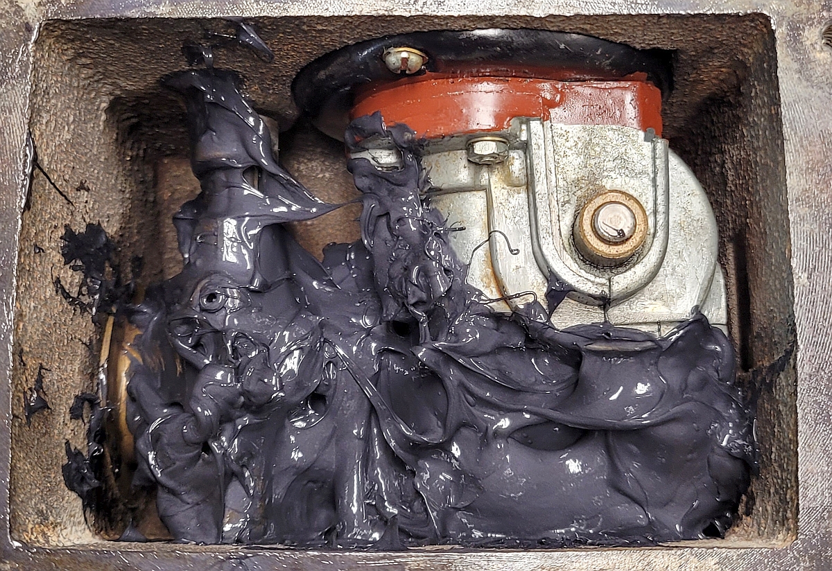
Two small screws remove the metal cover over the gearbox. Then its gasket can carefully be removed. With the cover off, you can see down inside the gearbox. There is supposed to be 4 ounces of NLGI no. 1 grease inside the gearbox. In this was maybe half an ounce of old grease which had dried. Operating the lever on the side of the gearbox separates the clutch halves, putting the machine in neutral. Releasing that lever is supposed to allow the clutch halves to be forced quickly back together by the clutch spring. In this case the dried grease's stickiness overcame the power of the clutch spring and the clutch halves never went back together again. I have seen this before and was confident that cleaning out the old grease and regreasing will make this gearbox work like new again.
Subassembly Reconditioning
Let's start with the terminal board. Most of the electrical wiring in this machine terminates on this board. It has six positions which are clearly labeled. This board is old - a code on a component in this machine indicates it was manufactured in 1978 - but beneath the dust it is still very usable. I made new resistor wires, replaced all 12 of the 6-32x1/4" brass screws, and generally cleaned things up a bit. I also tested the resistance. It measured about 280 ohms which is close enough to 300 ohms so that it should work fine. (After all, many resistors have +/- 10% accuracy.) This is what the terminal board looked like when I finished:
The reversing switch works fine despite being nearly 50 years old. It was made by Arrow Hart. The wiring had lost its color and the insulation was fraying so I replaced the switch wiring harness with a new one. It's nice when the wire colors match what's called out on the schematic.
The motor sounded fine when I test ran it. Its wiring is still sound and the wire numbers are intact and very legible. All I needed to do was clean off the old hardened grease. I did this very quickly in the parts washer. I didn't take a picture of the motor after cleaning, sorry!
As I received the machine, its clutch did not work. The reason it didn't work was that the grease inside the gearbox had dried out and hardened. It was sort of like very sticky molasses. The gearbox was small enough so I could put the whole thing into my little import ultrasonic cleaner. I used an industrial degreaser made by LPS, and I used it hot. I ran it for 60 minutes and that softened the grease enough so it came off easily with a little help from the parts washer and compressed air gun. With the grease removed, everything moved perfectly again.
The gearbox has a sheet metal cover. Mine was a bit dented. I hammered the dents out, cleaned it, and painted it black. I cut a new gasket and cleaned the cover screws.
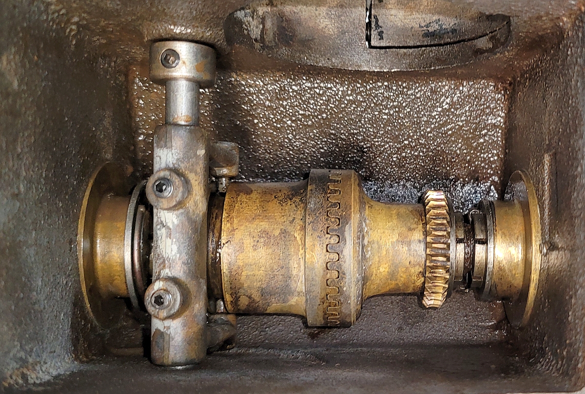
I have found that is is much easier to align the motor if I do it before adding grease to the transmission. There is a worm on the motor's output shaft that mates with a pinion in the gearbox (towards the right side of the picture shown just above). The motor's body is round and it goes through a round hole in the side of the transmission. After that, you need to worry about how far in the motor should go, and is the motor rotated so its worm is vertical. Anyway, you can pretty much tell how far in the motor used to be by the scuffs on its paint, and you can squint and kind of see how the worm lines up with the pinion. Once nearly there, you can gently tap on the motor with a screwdriver handle or something until the drive wheels outside the transmission have just a tiny bit of play but no more. Then the motor is clamped in place and 4 ounces of NLGI grade 1 grease is added. Compare the next picture to the one above which shows the old grease in the gearbox and you can easily see the previous mechanic in this transmission didn't put in nearly enough grease.
With the grease in, I put the cover plate back on with its new gasket, and the motor/transmission assembly was ready to go back into service.
Let's pause and think about what we've accomplished so far and what needs to happen next. We have cleaned up the wiring terminal board, replaced the wiring harness on the reversing switch, and cleaned the gearbox and put it back together with a new gasket. Incidentally, although the Airco Radiagraph is designed for a service life of many decades, there are things that can wear out on them. One such is the knurled drive wheels. These are made of hardened tool steel, and they are knurled to better grip the track. Over much use those knurls can wear down. So be careful if you buy a Radiagraph to check the condition of the knurls on the drive wheels. In this case, my knurls are still fine.
In a sense I've now done all the easy stuff. Still left to do are the main body of the machine and the governor/capacitor assembly. The main body is an iron casting with several small nameplates fastened to it. This particular body has some cracks in it which are going to have to be repaired. It also has some previous repairs that may need to be redone or at least cleaned up somewhat. In addition, each of the nameplates need to be removed and restored to legibility. Then the body will get painted and the nameplates will be reinstalled.
Let's talk about common problems found on old Radiagraphs. The gearbox can be gummed-up like this one was. Another common problem is that the knurled speed control knob doesn't rotate smoothly. Also, the wires leading from the governor to the capacitor can have damaged insulation to the point where the wires are in danger of breaking. Inside the governor, the brushes and brush holder can be worn or damaged, and the tracks on the governor plate where the brushes ride can be damaged. The governor's output shaft runs in small ball bearings and those may need replacing. Also, the indexed wheel can be slightly dented from rough treatment, and those dents can be preventing the wheel from rotating smoothly. Finally, the adjustment mechanism may have been lubricated with some kind of lubricant that dries sticky and gums up the works.
Before disassembling the governor, one needs to have firmly in mind that at each step you need to go slowly and make sure you understand where any shims are placed so that they can go back exactly where they came from.
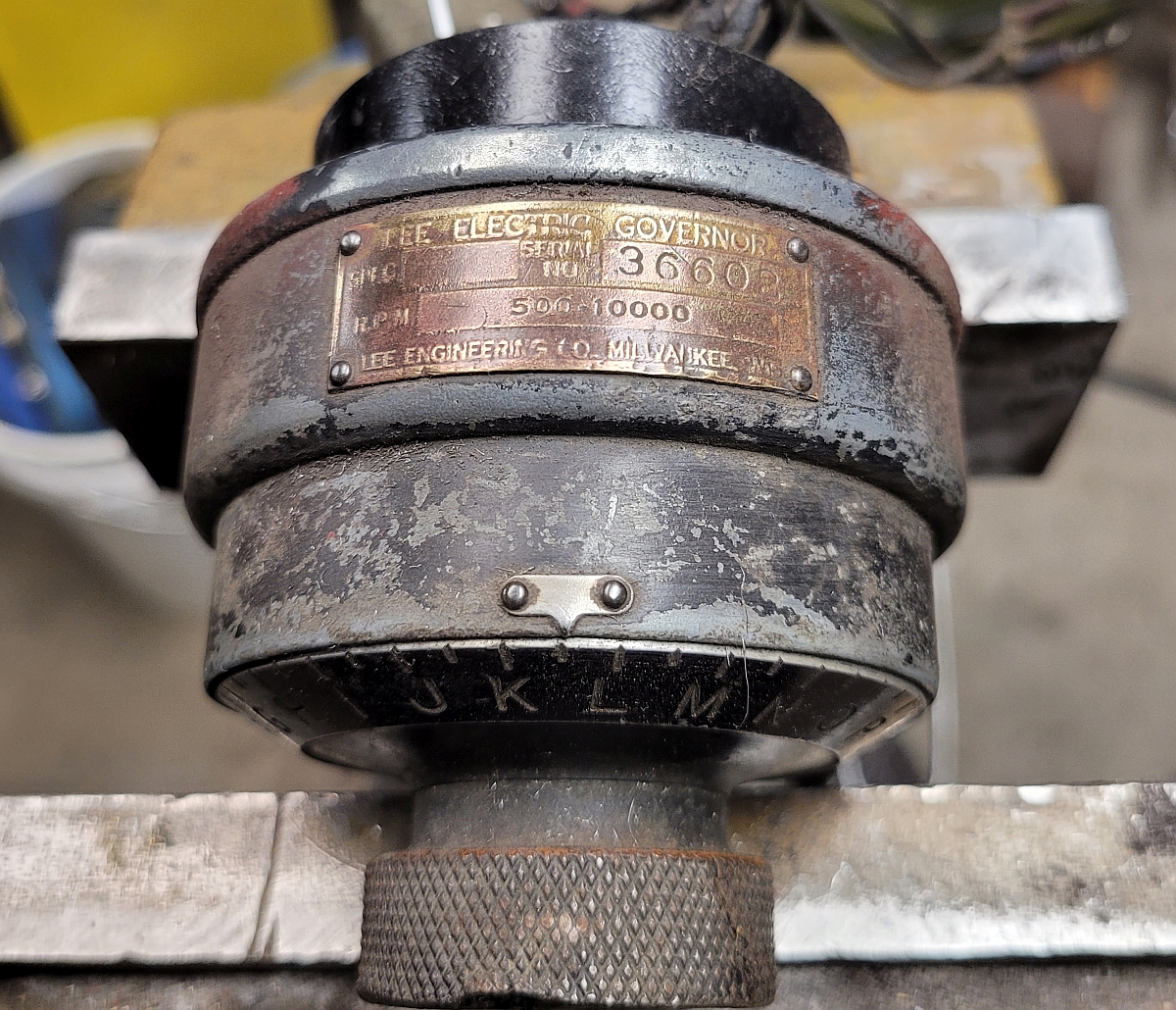
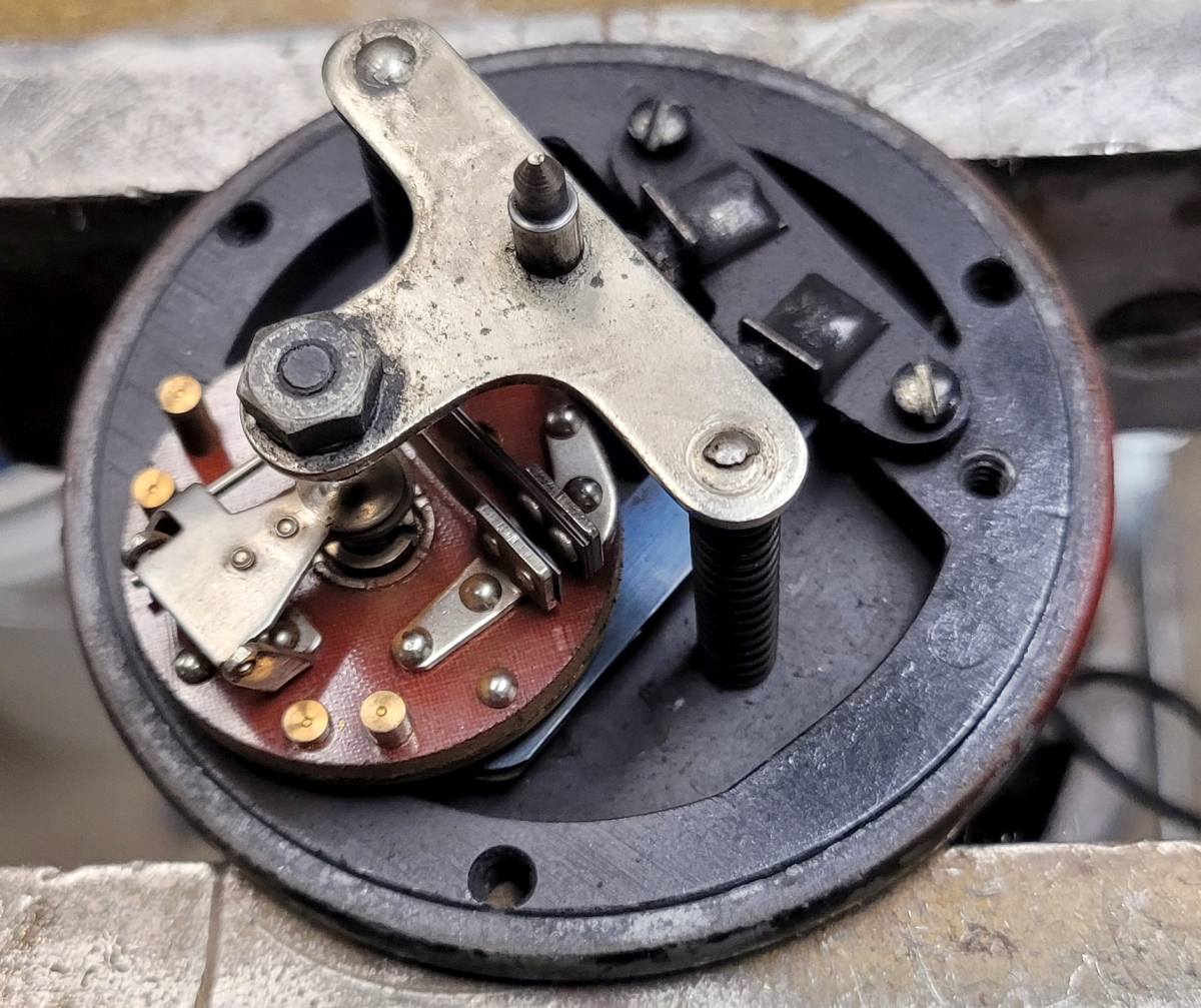
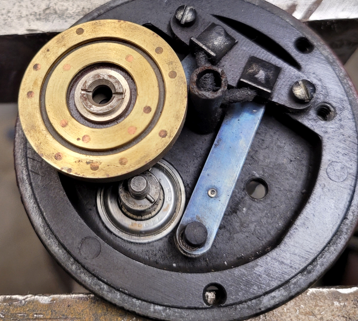
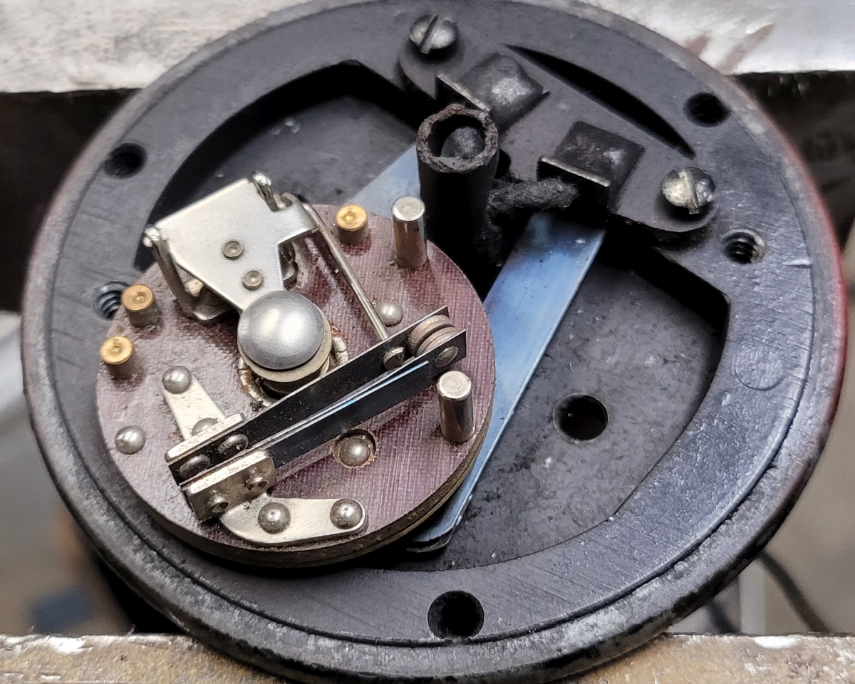
With no further ado, let's dive into restoring a Lee Electric Governor. Here you see the original governor assembly from this machine. I polished the nameplate with 0000 steel wool a little for legibility.
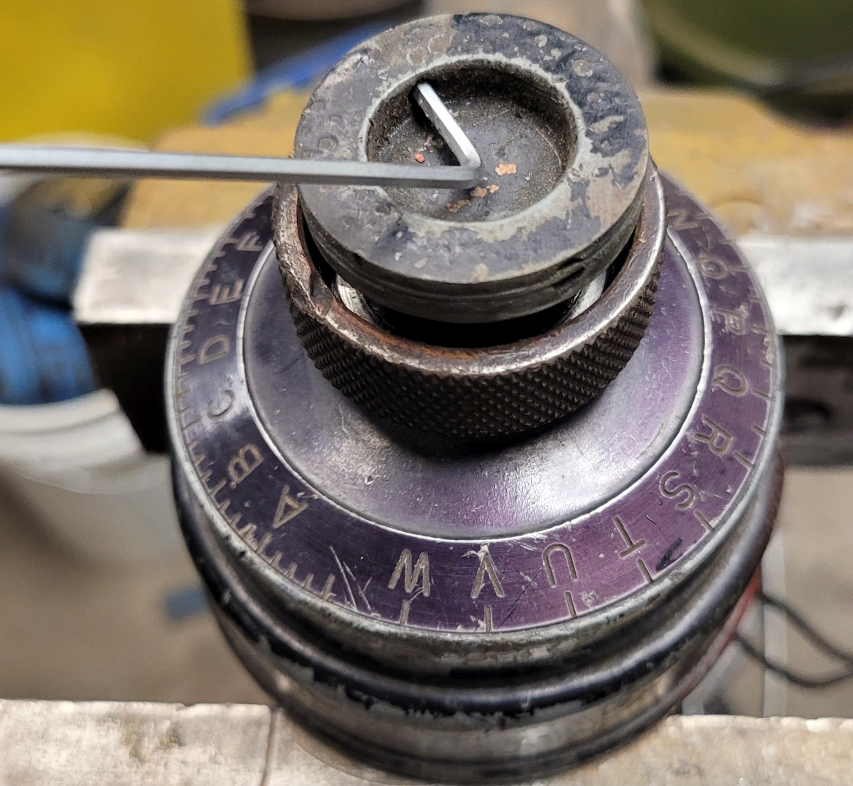
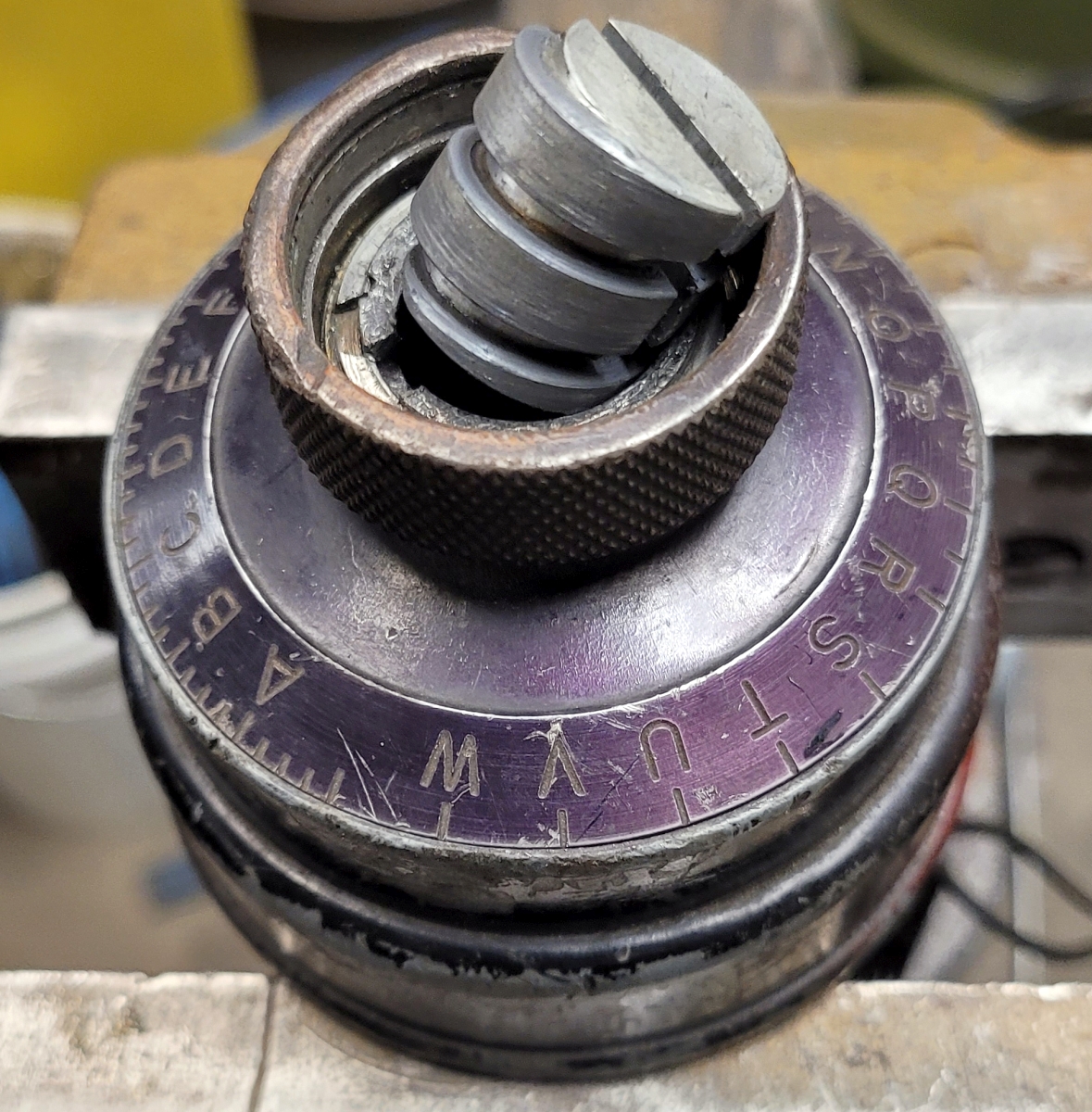
The knob in front is knurled, and also indexed with letters A-W. The first step is to remove the recessed disk in its center. Inside the recess are two very small holes across from each other. One (and only one) hole has a set screw in it. First, insert an Allen wrench and loosen it. Next, grab the Allen wrench with narrow pliers and, while holding the knurled knob firmly, twist the recessed disk counterclockwise and it will pop straight out. Some caution is needed because you only have hold of the tiny set screw in a hole, so don't let the Allen wrench slip out of the set screw. Here I have popped the recessed disk loose:
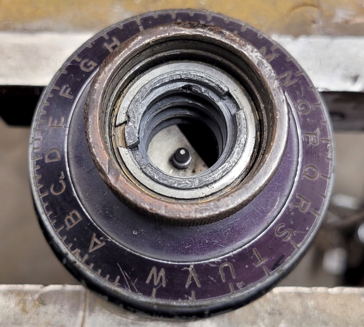
The recessed plug I just popped out turns an adjusting plug below. As you turn the recessed plug counterclockwise, the adjusting plug threads upwards. That's what pops the recessed plug out. This one was partway out and I just turned it out with my fingers. You can see the coarse threads on the side. Incidentally, I like to put a little very light grease on the adjusting plug. I've seen those bind up and it's not fun to have to take one apart if it's stuck.
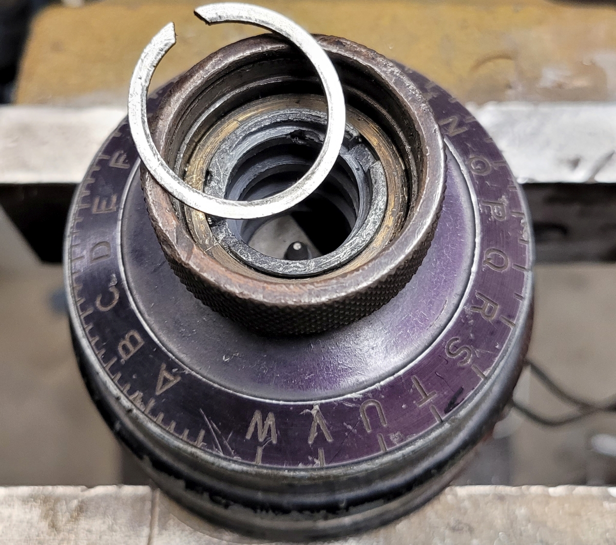
Now we're about to take off the indexed knurled wheel. But first there's a circlip that has to come out. It's a bit fiddly but there's no mystery to it. You can see it in this image:
Eventually, like all such things, the circlip will come off, hooray!
With the circlip out, before removing the knurled indexed wheel, I carefully remove and note the brass shim.
![]()
Now the knurled indexed wheel can be removed. Just below it is another shim. This one is wavy like a Belleville washer. I set the two shims aside and they were (initially) returned to the same place during reassembly.
![]()
Now I can remove the two fillister-head screws:
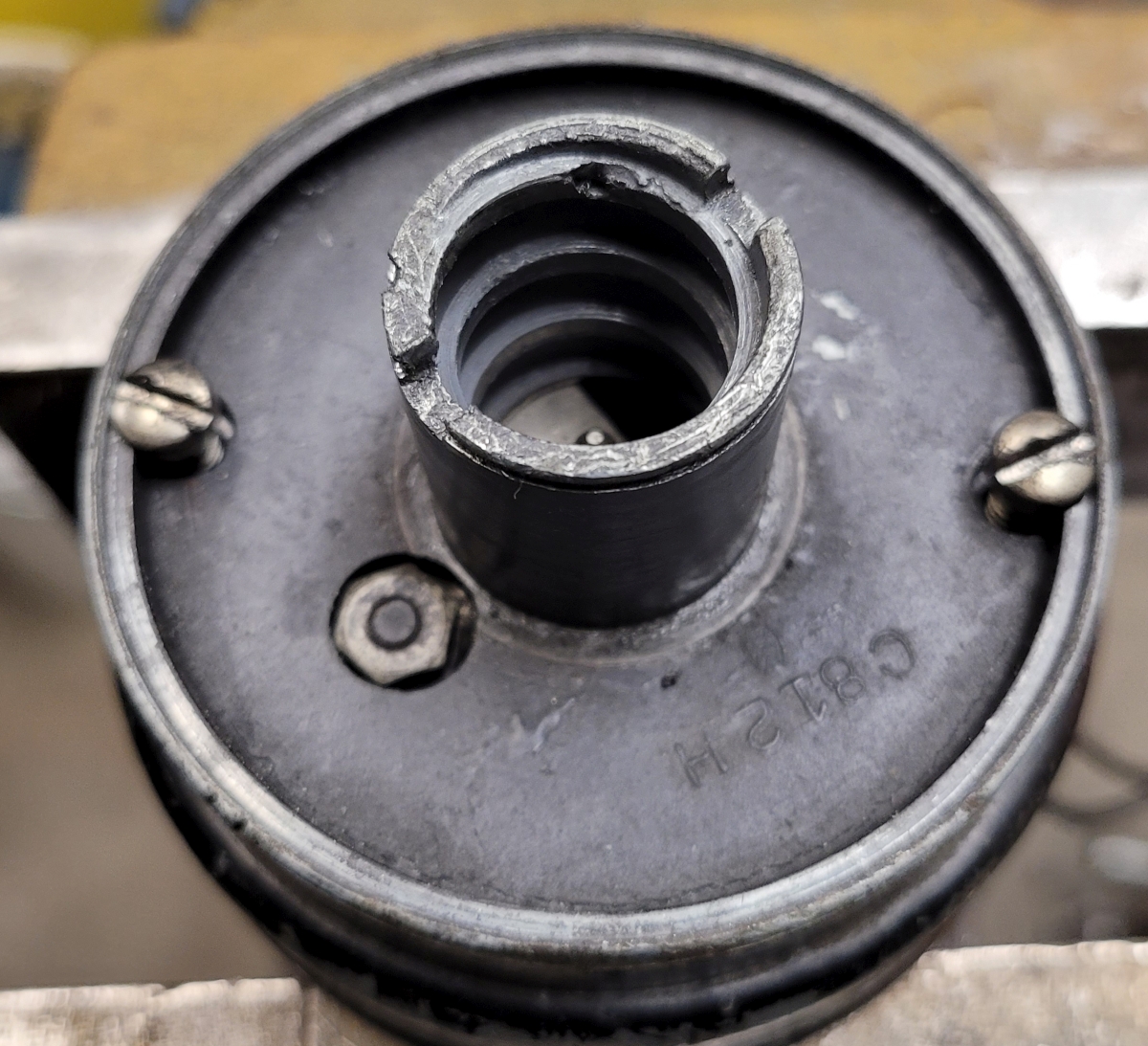
and lift off the governor housing, which exposes the governor plate and the control plate lever.
The control lever assembly just lifts off
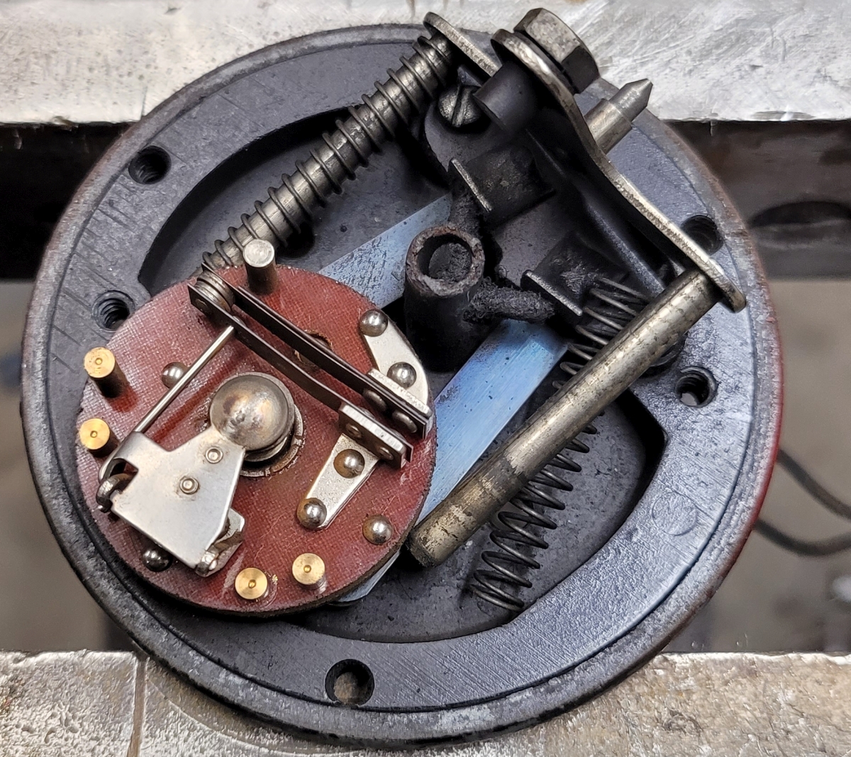
Now the actual round governor plate is exposed. There is a funny spoon-shaped object covering the center of it. You can just flip that to a vertical position. With that out of the way you can see the governor lock nut. To unscrew that nut you need to make a special tool:
Remove the governor lock nut with the special tool (made from a very old screwdriver). Note that this is a tiny part, easy to lose and almost impossible to replace or reproduce. I put a small wire tie through mine in a loop to keep it from running away.
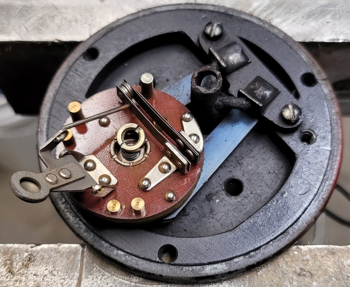
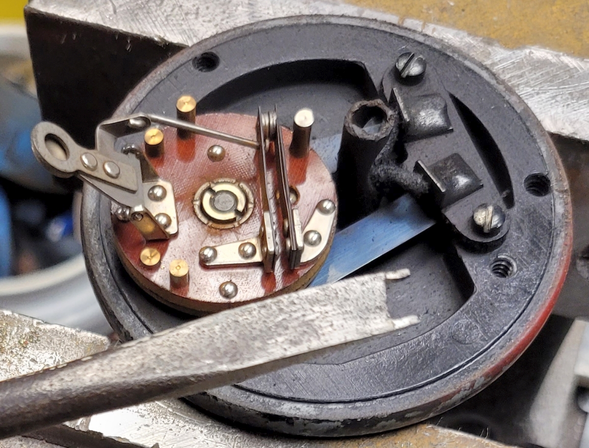
Then the governor plate lifts off. If you turn it over you can see the rings on the bottom where the brushes ride. If these rings are damaged you need a new governor plate.
With the governor plate off you can see the brushes and the top governor shaft bearing (New Departure 77038). These brushes are worn maybe 30%. Since I have new brushes, I will install those. Between the brushes you can see the top governor shaft bearing (New Departure 77038). I checked the top and bottom ball bearings and they were fine so I left them alone.
After closely examining my governor plate, its bottom rings were slightly tarnished, so I polished them with some 2000 grit crocus cloth.
And here she is, fitted with new brushes and a cleaned-up governor plate!
While I was in there I examined the wiring soldered to the lugs on the brush holder which goes down the nonconductive tube and out the bottom. The wiring looks just fine to me, so I won't replace it. It's not too difficult to desolder those 2 wires and make up 2 new ones and solder them on in their place had the situation called for it.
The only mechanical attention that this governor assembly might need now is to help the speed control dial turn smoothly. The castings that make up the body of the governor are pot metal, and these had a fair amount of white powder inside. I took a toothbrush-shaped wire brush and scrubbed all the sliding surfaces shiny. That really helped especially on the big coarse threads. I put a tiny coat of Sil-Glyde on the sliding surfaces and then everything moved smoothly.
There are 3 main body parts for the governor. There is the graduated dial with the knurled knob on it. That sits right on top of the governor housing. The 3rd part is just called the body. The graduated dial has a bore which closely fits the round boss on the governor housing (see the picture above where I removed 2 screws). The dial's bore has to be very clean and so does the outside of the round boss on the housing. This is one area where things can bind up if dirt gets in. Inside the round boss on the governor body are coarse threads. The part that screws into those threads is called the speed adjusting plug. The threads in that area must be wire brushed until they are spotless. It is imperative that these cleaning steps be followed until the assembled governor's dial moves very smoothly. Sometimes I have to repeat the cleaning steps several times. The good news is I get to be very good at taking the governor apart and putting it together again!
Remember the two shims, one wavy and one flat? Originally one went below and the other above the indexed dial. However, when I did that the dial didn't turn smoothly. To move it out just a little, I moved the flat shim from above it to below. That made it turn much more smoothly. Sometimes more shims have to be made, but this time I didn't have to.
Now let's start talking about cleaning the outside of the governor.
I removed the Lee Electric nameplate by tapping out its 4 drive screws from the inside of the governor housing. With it out, it was easy to polish it with steel wool. Besides that nameplate there is a tiny pointer which is also held to the governor body with drive screws. I cut very small pieces of masking tape to cover the pointer because I didn't want to paint over it.
Next I cleaned the governor parts and prepped them for paint. I wanted a sophisticated red color but wound up choosing "Cranberry". It's close enough, and the paint went on well. After the paint dried, it was time for final assembly. All throughout this entire rebuild, the capacitor (aka condenser) stayed wired to the governor. If you ignore all the complex and sophisticated parts of the governor, its root functionality is just to open and close points. It's like a highly controlled on/off switch. I believe the purpose of the capacitor is to prevent voltage spikes when the points open and close.
I tested the capacitor with my Fluke 87 meter. It tested fine so I decided to reuse it. (Sorry, no photo)
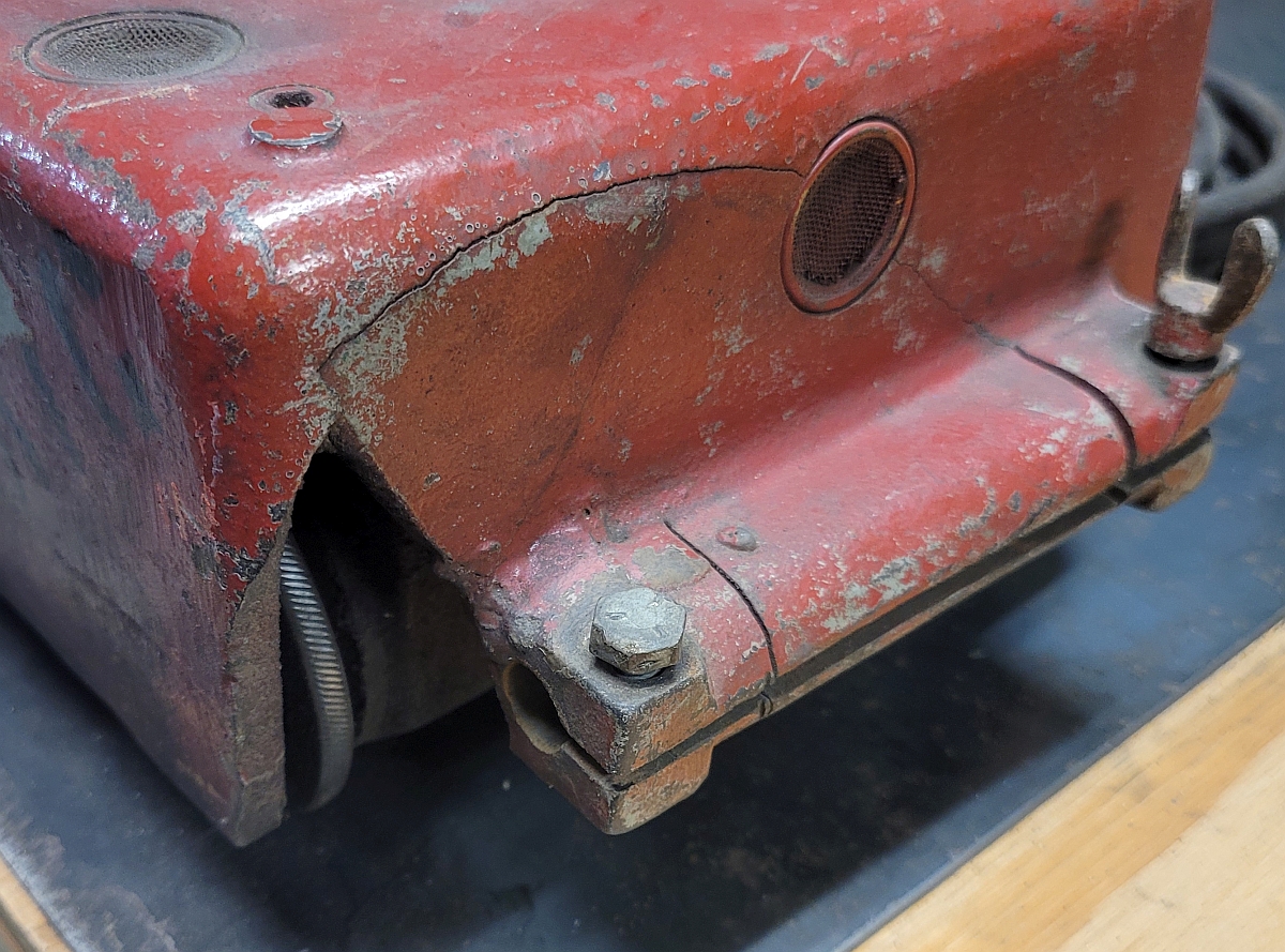
Leaving the governor rebuild for now, it's time to work on the cast iron machine housing. On a long cut, there is a temptation to leave the machine and go work on something else while it completes the cut. All too often, however, this results in the machine walking right off the end of the track and falling several feet onto its nose. The result can be as bad as the whole front of the case being broken away, or it can just be cracked, perhaps with a big piece missing like in this case.
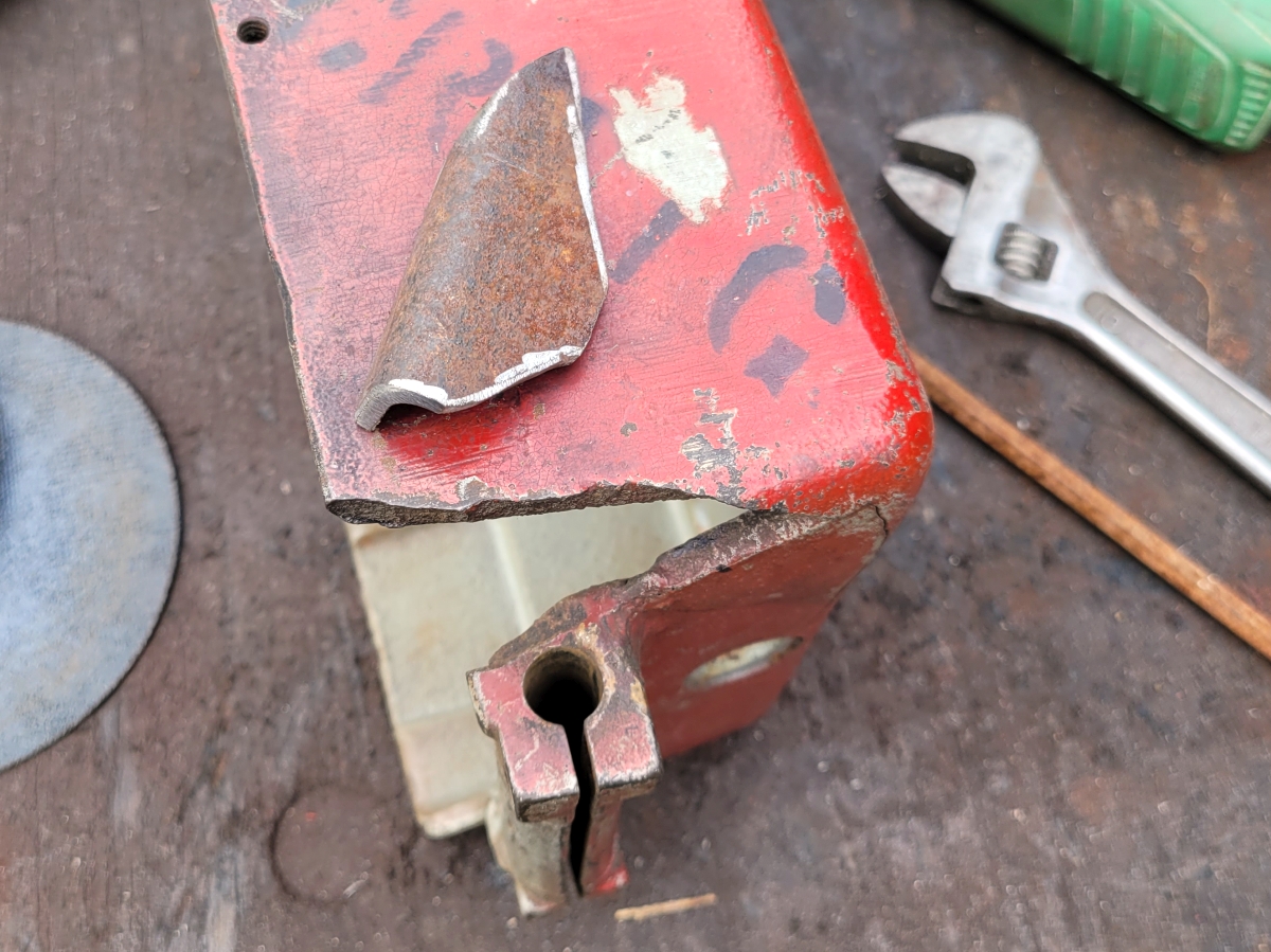
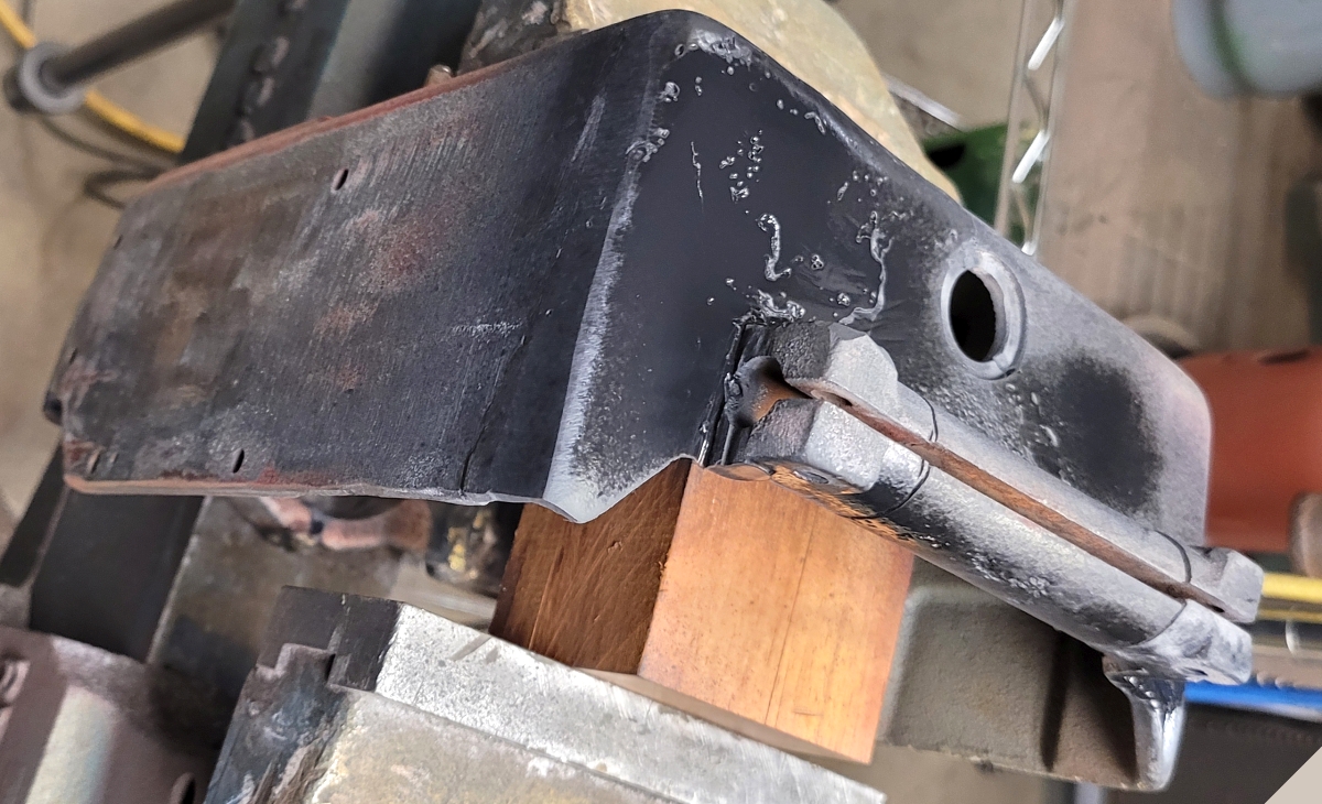
I have a friend who is a very skilled welder. He quickly fashioned a patch for the missing piece. The patch was cut from a piece of square tube 1/8x2x3" because its corner radius closely matched that of the machine housing. Here is a quick shot of the patch before it was TIG brazed in place:
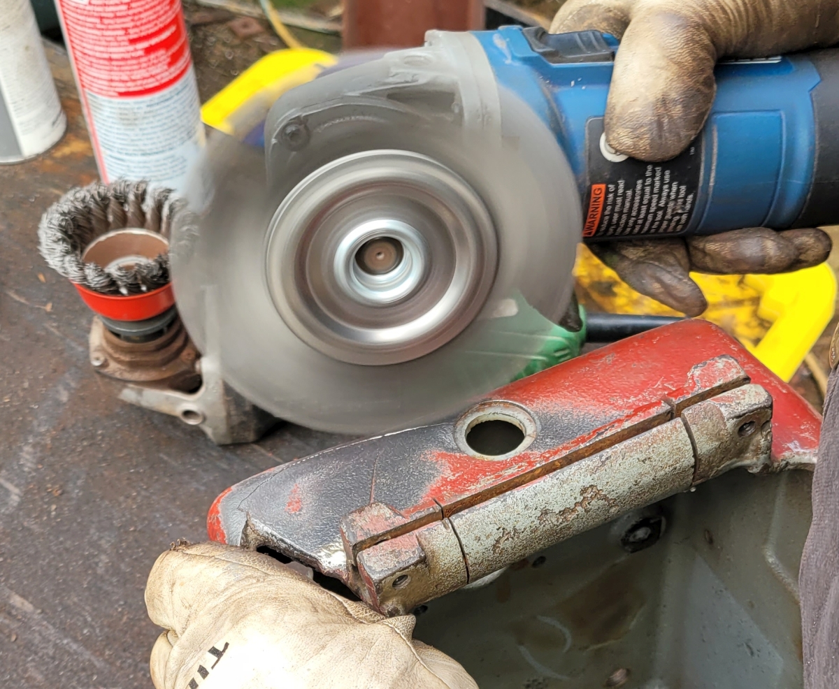
The cracks in the case were wire wheeled to remove paint, rust and other impurities. Here is a shot of the case being wire wheeled:
Later the cracks were veed out with a carbide burr in an electric die grinder. The next picture will give you an idea of how this vee grinding went:
Then the cracks were all either TIG brazed using silicon bronze wire, or TIG welded using nickel wire. I did not photograph the actual welding.
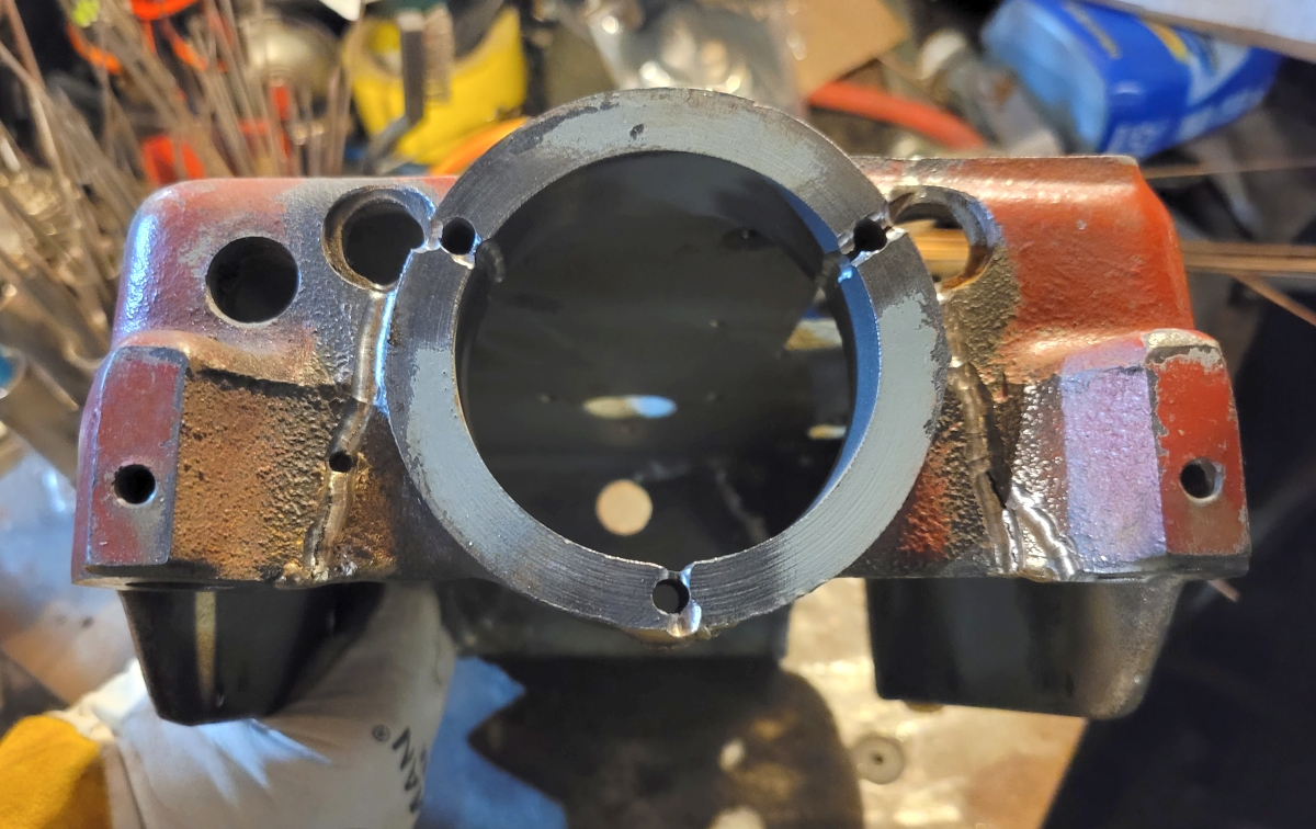
Here is a picture of the front end of the body, the one which was patched. The welds have been sanded and primed. I did some more weld blending later.
Cast iron welded with nickel is very hard. I was able to remove large bumps with a carbide burr in a die grinder, but it was slow and exhausting work. After a few hours I wiped the machine base down with thinner and spray painted it. You can still see where some welding was done, but welds sure look better than cracks. The base is now mechanically sound.
After painting the base, I set it aside to let the paint harden for a few days.
The first item to be reinstalled is the motor/transmission pair. A short digression: this track burner came with a (very rare) factory radius rod, so I've been thinking about how to cut circles and circular arcs. The radius rod has a center assembly which has a sharp point on it. You put that point into a center punch mark on your work. If you do things right, there is quite a bit of weight keeping that punch in the punchmark. You let the machine run on the workpiece and the rod makes it follow the radius. The two drive wheels are 6" apart on centers. If both wheels are kept fast to the axle, one wheel or the other must skid. These wheels are designed to be either fast or loosely mounted to the axle. If a wheel is not fastened to the axle it spins freely. Sometimes a wheel is even removed to add weight to the center point. I had never loosened or removed Radiagraph drive wheels, so I took the opportunity to teach myself how it's done. While each wheel was dismounted, I cleaned it and put a tiny amount of light grease on the axle. Now the wheels spin very freely on the axle when they are not pinned to a round groove on the axle. ;;; ADD PICTURE OF DRIVE WHEEL
I then mounted the motor/transmission assembly into the machine base using brass 1/4-20x1" socket head cap screws. The next thing to put in is the governor assembly. The governor shaft goes into the rubber flexible link. The link is secured to the governor and motor shafts with set screws. There was a problem with the set screw at the motor end of the motor shaft - it was stripped out. I was able to use a small easy-out tool in a tap wrench to remove the set screw. Then I replaced the flexible link with a new one since I have a bag of them. The new one didn't want to fit over the 1/4" shafts so I used a 1/4" chucking reamer to clean out the bores of the ends of the flexible link. Then installation went easily, and the problem of the stripped set screw was fixed.
Other miscellaneous issues I fixed: the transmission lever's vertical shaft was slightly corroded and hard to install and operate. I polished it, installed it and adjusted it. The stop pin for the trans lever was also polished and installed. Neither rear caster wheels turned smoothly, so I removed the axles and filed hammer burrs off the ends. With oil, they now turn fine. In use, the caster axles are supposed to be oiled weekly. I try to just oil them each time I use the machine.
Next I installed the governor. I discovered that screwing in the socket head cap screws went much easier with a shortened 5/32" allen wrench. Full length hex wrenches aren't able to fit down inside the machine base far enough.
Then I installed the switch plate and switch. Also I put in the (new) power cord in a new cord grip. With all of the components in place, it was time to reconnect the wires. I'd written down which wires go where, which made putting them back a lot easier. One thing I should mention is that from the factory, the wiring cable from the switch going over to the terminal board is routed under the motor. This keeps it well away from the spinning flexible link. Another thing that makes rewiring easier is to do all of the wiring first, and only after it's all done is the terminal board screwed to the inside of the machine body. ;;; ADD PICTURE OF COMPLETED WIRING
After wiring is complete, the motor can be test run. It's important that the motor speed can be varied over its complete range. Another thing to test is that the switch body is put in correctly. When it's correctly installed, pushing the switch lever forward makes the machine move forward and vise versa.
Thanks for reading!